Project Title: 3-D Redundant Manipulator Arm with Handheld Controller
Member Names:
Shane Larkin - larkinsh@umich.edu
Melany Mioduszewski - melanym@umich.edu
Project Description
Our robot is a four-link, RRRR, redundant manipulator arm that we designed and constructed from scratch using acrylic. The end of the arm is fit with a gripper of our own design that we ultimately want to use to pick up and place objects (see Objectives section). The joints of the robot are powered by hobby servo motors which are controlled by an Arduino Uno microcontroller. The robot features a hand-held controller that has two joysticks and a slider. One joystick controls the x and y velocities of the end-effector in the base frame while the other joystick controls the z velocity of the end-effector. The slider is a linear potentiometer that is used to open and close the gripper of the robot. The microcontroller reads the joysticks and maps them to desired velocity. This desired velocity, along with the right-pseudo inverse of the Jacobian is used to calculate the joint angles needed to achieve the desired motion.
Objectives
The objectives for our project were first to design and construct a 3-D robotic manipulator arm using servo motors. We then wanted to implement differential inverse kinematics principles to control the velocity of the robot arm end-effector in the base coordinate frame. The desired velocity would be input by the human controller via two joysticks. The final objective was to control the robot such that the gripper on the end of the arm could be used to pi
ck up and place objects accurately using only the joysticks to provide a desired input velocity relative to the base frame.
Pictures
Here's a picture of our robot along with the hand-held controller
Here's a close-up of the gripper. You can see the gears that are used to drive the pincers through the clear top plate.
Model
From the D-H Parameters, we calculated the following homogeneous transforms:
We then calculated the Jacobian, shown below:
J(1,1) = cos(th1)*(a1 + d2) + d3*cos(th1) + d4*cos(th1) + a4*cos(th4)*(sin(th1)*sin(th2)*sin(th3) - cos(th2)*cos(th3)*sin(th1)) + a4*sin(th4)*(cos(th2)*sin(th1)*sin(th3) + cos(th3)*sin(th1)*sin(th2)) - a2*cos(th2)*sin(th1) - a3*cos(th2)*cos(th3)*sin(th1) + a3*sin(th1)*sin(th2)*sin(th3)
J(1,2) = a4*sin(th4)*(cos(th1)*sin(th2)*sin(th3) - cos(th1)*cos(th2)*cos(th3)) - a4*cos(th4)*(cos(th1)*cos(th2)*sin(th3) + cos(th1)*cos(th3)*sin(th2)) - a2*cos(th1)*sin(th2) - a3*cos(th1)*cos(th2)*sin(th3) - a3*cos(th1)*cos(th3)*sin(th2)
J(1,3) = a4*sin(th4)*(cos(th1)*sin(th2)*sin(th3) - cos(th1)*cos(th2)*cos(th3)) - a4*cos(th4)*(cos(th1)*cos(th2)*sin(th3) + cos(th1)*cos(th3)*sin(th2)) - a3*cos(th1)*cos(th2)*sin(th3) - a3*cos(th1)*cos(th3)*sin(th2)
J(1,4) = a4*sin(th4)*(cos(th1)*sin(th2)*sin(th3) - cos(th1)*cos(th2)*cos(th3)) - a4*cos(th4)*(cos(th1)*cos(th2)*sin(th3) + cos(th1)*cos(th3)*sin(th2))
J(2,1) = a2*cos(th1)*cos(th2) - d3*sin(th1) - d4*sin(th1) - sin(th1)*(a1 + d2) - a4*cos(th4)*(cos(th1)*sin(th2)*sin(th3) - cos(th1)*cos(th2)*cos(th3)) - a4*sin(th4)*(cos(th1)*cos(th2)*sin(th3) + cos(th1)*cos(th3)*sin(th2)) + a3*cos(th1)*cos(th2)*cos(th3) - a3*cos(th1)*sin(th2)*sin(th3)
J(2,2) = a4*sin(th4)*(sin(th1)*sin(th2)*sin(th3) - cos(th2)*cos(th3)*sin(th1)) - a4*cos(th4)*(cos(th2)*sin(th1)*sin(th3) + cos(th3)*sin(th1)*sin(th2)) - a2*sin(th1)*sin(th2) - a3*cos(th2)*sin(th1)*sin(th3) - a3*cos(th3)*sin(th1)*sin(th2)
J(2,3) = a4*sin(th4)*(sin(th1)*sin(th2)*sin(th3) - cos(th2)*cos(th3)*sin(th1)) - a4*cos(th4)*(cos(th2)*sin(th1)*sin(th3) + cos(th3)*sin(th1)*sin(th2)) - a3*cos(th2)*sin(th1)*sin(th3) - a3*cos(th3)*sin(th1)*sin(th2)
J(2,4) = a4*sin(th4)*(sin(th1)*sin(th2)*sin(th3) - cos(th2)*cos(th3)*sin(th1)) - a4*cos(th4)*(cos(th2)*sin(th1)*sin(th3) + cos(th3)*sin(th1)*sin(th2))
J(3,1) = 0
J(3,2) = a3*cos(th2 + th3) + a2*cos(th2) + a4*cos(th2 + th3 + th4)
J(3,3) = a3*cos(th2 + th3) + a4*cos(th2 + th3 + th4)
J(3,4) = a4*cos(th2 + th3 + th4)
Block Diagram
Controller Design
Our controller uses principles of differential inverse kinematics in order to control the robot. The desired velocity is input to the Arduino through the joysticks and linear potentiometer found on the handheld controller. We then calculate the right-pseudo inverse of the Jacobian using the current angles of each joint. We use the right-pseudo inverse because this is a redundant manipulator, so the Jacobian is not square. To calculate the desired joint velocities, we multiply the Jacobian by the matrix of desired end-effector velocities. We then numerically integrate each joint velocity using Euler’s Method to obtain the desired joint angles for each time step. These values are then written to the servo motors controlling the joints.
Implementation Notes
The robot was built from five servos (one high torque) and acrylic links. The links were designed in Rhinocerous and laser cut according to the design shown below. 6 mm thick acrylic was used for link 1 and all others and the base were cut from 3 mm acrylic sheets. The piece connecting the links to the base servo was cut from acrylic which was then heated and bent into the correct position. The gripper is powered by a mini servo and which is controlled by a soft potentio meter. It is composed of a base plate, the two geared arms, and a top plate. During construction, the servos were attached into the links with screws and epoxy. The base servo was wired into a brace and fixed to the underside of the box with epoxy. The base supports the arm and hides the Arduino and powerstrip for the servos (which are all powered by an external DC source).


The controller was also cut from acrylic and contains two joysticks and a soft potentiometer. All the components are powered by the Arduino so a cable connects it to the robot’s base.
While constructing the robot, we also modeled it in MATLAB to check the validity of our Jacobian and homogeneous transforms. We then transferred our MATLAB code into the Arduino, utilizing the MatrixMath Arduino library in order to do matrix operations, and tested it out on the robot.
Results
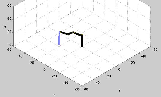
Before implementing the physical robot, we first modeled it in MATLAB to make sure that our mathematical model for the Jacobian was correct and that velocity commands would work properly. The pictures below show the final position of our robot after being given commands to move in the x, y, and z directions, respectively. We used these animations to convince ourselves that the Jacobian that we calculated was generally correct.
X-Velocity Command
Y-Velocity Command
Z-Velocity Command
After checking things out in MATLAB and finishing construction of our robot, we were finally able to test it out for real. Our first video shows our robot stretching out after being powered for the first time. There are obviously some bugs to work out but it moves!!!
In the next video, the robot is actually responding to input commands from the joystick. We see pretty good results in the z-direction as the robot moves up and down. However, there is some drift where the base of the robot is turning as the end-effector is moving up or down. We don’t want this to happen so we still need to tune up the controller.
In this video we have the gripper up and running! We’re even able to grab something with it (even if it is the robot’s own cord)! But we’re still seeing that drift…
Finally, we see vertical motion with little to no drift in the x or y directions! Now we need to get some motion in the x and y directions.
In our final video we see vertical motion with little drift and also some lateral motion. At the end of the video, you can also see the robot approach a singularity and freak out due to the loss of a dimension in the Jacobian.
Discussion
From our results, you can see that we came pretty close to achieving our final goal of being able to pick up an object. We fulfilled our objectives of constructing the robot and then getting it to respond to commands input from the hand-held controller but unfortunately we ran into some problems that prevented us from reaching that final objective. But first, the good news…
We eventually got the robot to move in the z-direction of the base frame when we input a desired z-velocity using the joystick. So, when pushing on the z-joystick, the robot moved ONLY in the z-direction, which we think is a big success! We also were able to achieve motion in the x and y directions as seen in our last video. This motion was not as precise and was subject to more drift but would still give us enough precision to pick up an object. Finally, we were able to get the gripper moving and even have it grab a wire of the robot.
Unfortunately, soon after our final video was created, we had a number of problems. One of our servos burned out and we had to find a replacement and then dismantle the robot in order to fix the problem. Also, one of the pins on a joystick broke off, so we had to switch around our joystick wiring to a format that made less sense. We ended up with controls for the y and z velocities on the left joystick and then x velocity on the right joystick. After these changes were made, the robot did not work nearly as well. It jerked around much more and exhibited drift similar to what we saw when we were first controlling the robot. This could have been due to poor connections on the joysticks, wires shorting, or some bug in the code. Unfortunately, due to our time constraints, we were unable to identify the problem and are left with the robot working with a large amount of drift.
Overall, the fact that we designed and built our own robot definitely set us back due to the mechanical problems that had to be overcome before being able to program the robot. These issues gave us less time to debug our code and fine tune our controller but we believe that we learned a lot from the whole process and are very pleased with the good results that we obtained. This robot is well on its way to achieving that final goal of accurately picking up objects!


